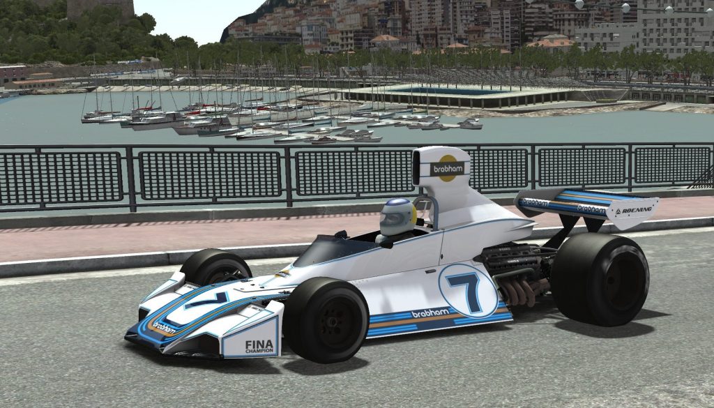
I know people have been waiting for this for some time. What process do I actually use to create the tyres? What data do we need, and how do we use that data? These questions are deep and will have to be covered over at least a couple separate blogs. The first area is always going to be the data collection phase, and initial implementation, this is what I’m covering this week.
Research/Data Phase
This is a fairly time consuming aspect. You need to start here, you need to gather as much information on your tyres as possible. As long as it’s reliable, more data is always helpful. The key word here being reliable. The problem for most, is that you’ll likely have to rely on data from the internet. Even for those more fortunate, who are blessed with manufacturer data, tyre data is seldom measured in a way that correlates very well to real life. Niels Heusinkveld covers this well in an older forum post available here. The gist is that raw data is noisey, provided data may have been poorly ‘fit’ and incomplete and that surfaces and machines can produce vastly different results. Because the temperature of a tyre changes quickly with a little sliding, for example, a sweep test will yield different results loading up the tyre (upswing), compared to unloading of the tyre (downswing). Many video examples exist regarding how tyres are measured, for those interested. One such example can be seen here. In any case, we’ll try and outline useful data through a sort of list of what is required, and how it can be used. Obviously, we need to know the tyre size and any other codes (compounds, tread pattern, etc). The size for the Brabham BT44B, was collected during the first blog, when selecting placeholder tyres. As a reminder, they are Goodyear 9.2/20.0-13″ for the front and 16.2/26.0-13″ for the rear. Clearly, these are imperial units and the first number represents tread width, followed by overall diameter and finally rim bead diameter. It does not seem possible to buy these tyres from Goodyear anymore. Given the time that has elapsed since these were new, it also seems unlikely to get originals or that manufacturers would still have the data concerning them. Furthermore, if you could get your hands on 40 year old tyres, some of the data will be poor quality. Shore A hardness readings for example, would be completely irrelevant as tyres significantly harden with age. It’s always a good idea to ask manufacturers, which I have done. Unfortunately, I did not get back any meaningful data, other than some tidbits. Therefore, I’m going to have to find my own data. This is also partially why the Brabham was chosen as the blog car, because we knew manufacturer data would be scarce (and/or obsolete), and so the rules of confidential data need not apply. This then forces me into a situation most modders find themselves in, hopefully making the blog more relevant.
The closest current offering Goodyear has for the fronts are 9.5/20.0-13’s. This is listed in their vintage Sports Car Catalogue. Interestingly the catalogue actually lists them as having a 9.1″ tread width. This means they are likely very similar to the grand prix tyres of old. The application is listed as “FA” presumably referring to Formula Atlantic. A series which began running in the 1970’s. Obviously, they were not as quick as grand prix cars, having only 1.6L engines, and so likely also have slightly different tyre constructions.
Meanwhile, Avon seem to have taken up the near exclusive challenge of supplying historic tyres for older racing cars. Some basic dimensional specifications can be found at their website. These sources, combined, are still not really adequate to fully replicate these old tyres. So we have to continue searching, but at least we’re making some headway.
The 1970’s and 80’s…
So what do we know about 70’s F1 tyres? Generalized information can still be helpful. We know they were a bias-ply construction as Michelin introduced the first radial in 1977. If we travel back in time to 1975, what literature and/or data is out there? Untimately, not much. What we do know is that Goodyear had just come out on top in the tyre wars and didn’t need to develop heavily as a sole supplier. This wouldn’t be the case in 1977, as I mentioned previously, when Michelin would introduce the radial tyre to F1. Either way, this particular fact is irrelevant to us. The fact it was a slight lull in competition however, is relevant. Even though Goodyear would continue with some development in this time, it’s not likely they would have felt the need to play around with complex tyre structural changes to keep exploring the limits. Interestingly, even in the early 80’s Goodyear would keep the bias-ply competitive with Michelin, until finally succumbing and adopting the radial construction type in 1984. Unfortunately, information covering F1 tyres of any sort seems exceptionally hard to come by (and if anyone has found some good literature, I implore you to come forth and reference your source in the comments section). It would seem sensible that Goodyear may have indeed adopted some of the techniques of radial tyres and probably used something more like a ‘belted bias’ tyre in the early 80’s. This wouldn’t have been the case in the mid-70’s. One key source of data are old race reports. We can gather that tyres lasted the full race, without the need to change them unless damaged. Though pit-stops times had started to improve by then, it would seem the benefit of fresh tyres was still lesser than the time required to change them.
More on Construction Types
Tyres are complex, damn complex, feats of engineering. Sadly, this is a world steeped in mystery, secrecy and even ignorance. So I will try and share some of my knowledge, especially thinking in terms of what could help modders. In terms of construction, we have the 2 main philosophies, bias-ply and radial. The first, and earliest construction type is the bias-ply (AKA cross-ply). The main construction differences between the two are outlined reasonably well at Michelin. That said, construction is often complex and giving them these labels may even be partially misleading as construction designs can incorporate design elements of ‘competing’ methods. The belted bias tyre is a third design which broadly speaking, is acknowledged as a hybrid of the two. A belted-bias tyre is essentially just a bias-ply tyre with an additional ply layer, called a belt layer. Normally, the belt ply in a belted bias tyre operates at similar ply angles as the supporting carcass beneath. However, an exception to that ‘rule’ (rules are meant to be broken, after all) would be drag racing belted bias tyres, but I’ll come back to this later.
The Bias-Ply Tyre
What do we know about them? How do they relate to 1975 Grand Prix tyres? I’ve already outlined my suspicion that they were likely to be a more ‘conventional’ tyre of bias-ply. What I mean by that is, an even number of plies, running at exactly opposing angles. They probably numbered 4 in total, as was common practice, as 2 likely wouldn’t have been sufficient to curtail the enormous growth of the tyre at GP speeds (top speeds of around 310-320km/h). We also see that the higher the speeds required, the lower the ply angle in the crown of the tyre tends to be. This is again, to resist growth of the tyre at speed, and keep the tyre flatter at speed. If you imagine a tyre with radial plies only (operating @ 90° to the direction of travel, i.e. bead to bead). Such a construction would essentially create a round tyre at high pressures and or speeds, significantly narrowing the useful part of the contact patch. A hypothetical tyre with a 0° belt would stabilize and severely inhibit growth due to rotation, but would not provide any lateral support. Therefore, lowest ply angle for a bias-ply is typically around the 26° angle, with high performance road tyres in the range of 30-35° and normal tyres of the time around 38-40° (ref: page 8, Continental). Depending on the construction, the ply angle may also gradually increase nearer the bead of the tyre as explained under the bias-ply section of this Wikipedia entry. Therefore, those previously mentioned angles are typical crown / tread angles. The crown is simply the ‘treaded’ area of the tyre, the part which is intended to contact the ground in normal use.
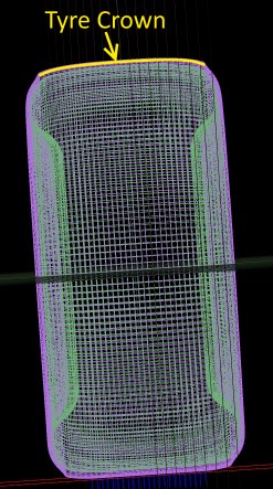
A visual representation of the tyre crown from tTool
As a result of their structural attributes, bias-ply tyres also generate more friction between internal components. As a consequence, bias-ply’s generate more heat and have higher rolling resistance. This is due to flexing in the tread area, where inter-ply movement is far greater than with a radial. On the other hand, they also have a more forgiving nature and typically generate grip at higher angles of slip. The bias-ply was phased out very slowly since the inception of the radial in 1948, by the early 70’s, radials were the common theme for road cars, which were the first to adopt the new technology. The first race cars to use radials were Grand Prix, beginning in 1977 with Michelin. Since then, most major racing categories have adopted them, with NASCAR being one of the last to make the move in 1994. Lower tier categories may still use bias-ply tyres, such as Formula SAE, and while we certainly see them in karting.
The Radial Racing Tyre
A “perfect bias” would hypothetically be 45°, although it seems hard to find a clinical definition of where the cut-off is. It seems that a radial would have to have it’s casing structure be closer to 90°, than 45° in the tread region. Does that mean 67.5° is the cut-off for the definition of a bias-ply tyre vs a radial tyre? I believe so. To confirm this, patents happen to be a good source for generalized or specific tyre properties. For example, this patent states that a bias tyre has a ply angle of “at about 25-65° angle with respect to the equatorial plane of the tire”, leading further credence to my cut-off threshold. Most high-end racing radials actually incorporate a casing structure that operates at an angle of approximately 70-75°, giving them some bias-ply strength in their sidewall, while retaining the definition of a ‘radial tyre’. Racing tyres therefore, are really a hybrid of radial and belted-bias constructions. There may be other specialty tyres with ply angles of below 22.5° and such might be defined as another construction type altogether. Such tyres are unlikely to be used on race cars, or any other cars for that matter. If such a tyre exists, it would likely be reserved for novelties, such as for R/C (remote control) cars or similar atypical tyres. Radials are often more complicated though, tending to have a 0-degree ‘belt’ laid atop of the main belt, usually made of nylon or rayon. This is known as a cap-ply. This my not stretch the entire tread width either, and in the case that is covers only the shoulders, is known as a shoulder-cap ply. The purpose of such a “0-degree” belt is almost always to improve high speed stability of the tyre. For road cars, shoulder-cap plies are intended to reduce potential fatigue by softening the harsh transition from belt to sidewall. The edges of the belt can actually cut into the tyre, potentially damaging the rubber and carcass plies, eventually leading to failure. Even though race car tyres take far more abuse, they have a typical service life of only 50-1000km. As such, the overall fatigue resistant requirements are still lower.
To help visualize the different sections and components of the tyre, you may find the following diagram useful:
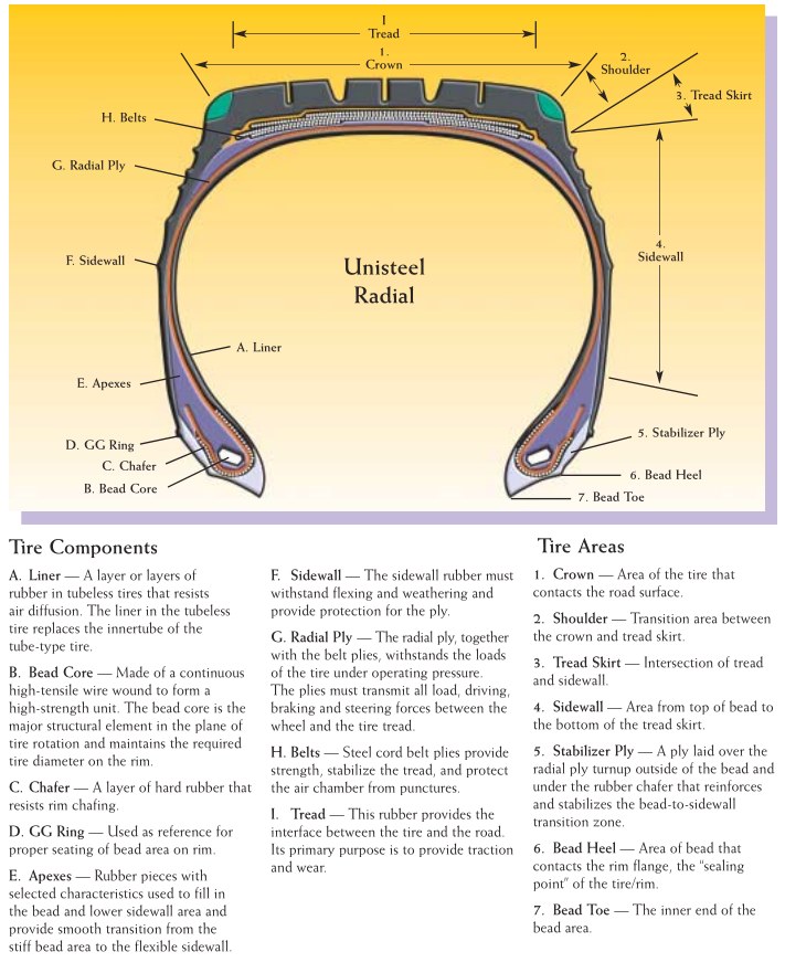
Tyre component diagram. (Ref: Page 6, Goodyear Radial Truck Tire And Retread Service Manual)
Please note that different engineers will use different terms to describe certain parts of the tyre. For example, one might call the rubber surrounding the bead, a filler rubber, while others call it the apex rubber. A shoulder-cap ply may also be known as a shoulder-insert. A cap ply could be known as a stabilizer ply, undertread ply, or even a fabric-belt or simply a belt. So be aware of aliases, though most are somewhat intuitive.
The belted-bias tyre
Belted-bias tyres are somewhat rare. Despite ‘racing’ tyres often being called a hybrid of radial and bias-ply tyres, not many actually fit the definition of a belted-bias tyre. Belted-bias tyres are essentially a bias-ply tyre with a ‘belt’ or ‘breaker’ layer in the tread section to improve rigidity. This belt ply tends to have a similar or slightly lower angle to the carcass plies that lie directly beneath. An exception could be drag racing tyres, which often have near 0° belts. This is due to the desire for additional strength only in the longitudinal direction. So for optimum longitudinal grip, tyres should generally have a near 0° belt. On the other hand, optimum lateral grip may be achieved with an approximate 30-33° belt angle. This mostly applies to radial tyres, as the structure of the carcass can influence this, but the general principal remains valid for belted tyres or even raw bias-ply tyres. As tyres are rarely designed for either application in isolation, typical belt angles operate in the 15°-27° range.
With all this in mind, I am constructing the Brabham BT44B tyres with a 4-ply bias-ply design. Using Nylon cord, and a crown belt angle in the region of 25-26°, about the lowest you’ll see with a bias-ply tyre.
Required Data
Mass
Why this is important, I hope is obvious enough. In detail however, it will help with a few things than is intuitive. It’s necessary in helping calculate the overall unsprung mass of the vehicle. Furthermore, knowing this will help determine certain tyre properties. In the case of the BT44B, despite their enormous stature, the rear tyre is only (approximately) 12kg, while the front tyres were about 5.3kg. Bias-ply tyres tend to be somewhat lighter than radials, this is mainly due to the lack of a heavy steel belt. However, as Kevlar belted tyres become available, negated much of this difference. Finally, knowing the mass of the tyre can also help us decide on how thick or dense the actual rubber materials might be. Slick racing tyres also have a typical tread thickness of 3-4.5mm (that’s the outer layer of rubber in the crown area). As we fill in as many known quantities as possible, we afford ourselves a better chance of bettering estimates of quantities for which we are unable to obtain data for.
Cross Sectional Geometry
The best is a diagram, a plot, CAD or scan of the tyre shape. This may or may not be difficult to come across. Failing that, at the minimum you’ll want a complete listing of overall dimensions (section width, radius, rim width and rim diameter, etc), along with high resolution photographs. A technique that you may want to employ is photo-overlaying. This can be done by trying to replicate the tyre state as much as possible, in tTool utilising the quasi-static analysis tool and comparing the results with photographs. Such as seen below:
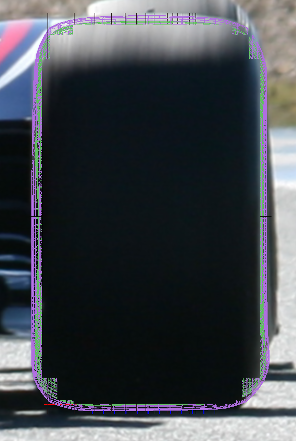
An overlay of an rF2 physical tyre over a real photo.
For example, a static photo would be great, but perhaps if you know the corner, you can approximate speeds and temperatures and pressures too, along with any external forces applied (as in vertical, longitudinal or lateral forces). You may even base those estimates on telemetry you created with a TBC model or pre-existing TGM tyres. For the cynical out there, you can consider doing this even if you have been provided with a cross-sectional tyre profile, as verification.
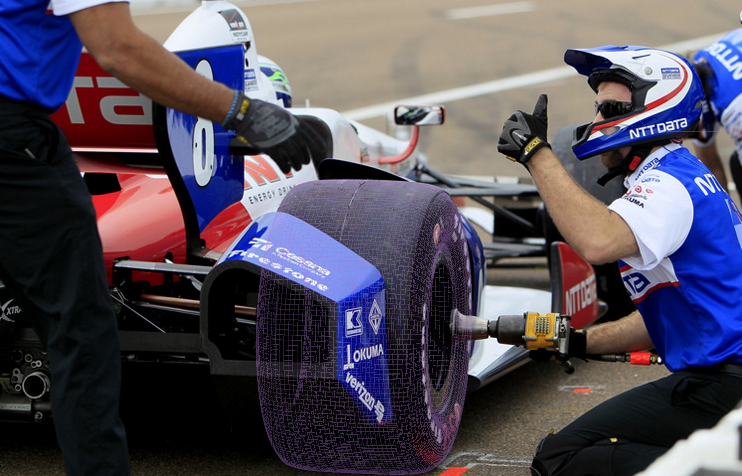
Another overlay of an rF2 physical tyre over a real photo.
To do this, you basically find an appropriate photo (long range high-zoom photos are best, to minimize perspective), and try to duplicate the camera positioning as much as possible within tTool. This won’t be easy, and will take some iterations. If your geometry is off, it’ll also make the process that much harder. Doing so requires some patience and a lot of alt-tabbing between rF2 and an image software. When you’re happy that you’ve matched the position and FOV, so much as possible, you can grab a screenshot with F12. The camera manipulation keys in tTool are the num-pad keys while holding modifier keys Ctrl & Shift as needed. At this point you’ll probably want to create a new layer in the real life photo’ and make that layer semi-transparent, I generally use about 50% opacity. This may help you to make fine geometry adjustments to your tyres.
Construction Materials and Properties.
At the minimum you’ll need to know the construction type (that is radial, bias-ply, or belted-bias). If you have access to the tyre, but you can’t dissect it, without tearing a tyre apart, you can still measure the thickness with a long reach caliper. Ideally you’ll want to do so across as many points as possible, as well as using the depth scale to measure the tread depth as well (if you weren’t able to come by this data). The key parts will be the thickness of the tyre at the bead, the minimum thickness at the sidewall, and the overall tyre thickness at the middle of the crown (the equatorial center of the tyre). As a ballpark, these figures can range from approximately 12-17mm, 3.6-7mm, and 7.8-22mm respectively. The large variance in the crown thickness concerns road tyres or wet tyres which have a deep tread designed to disperse significant amounts of water. Whereas a bias-ply slick will have the thinnest equator / crown center of all tyre types. The tread depth (or thickness) refers to the thickness of the outer layer of rubber. Tread rubber is the only part of the tyre for which adhesive grip is a high priority. Whereas the rubber below will be a ply casing rubber, designed to bond the tread to the tyre casing or belt or cap-ply. Generally, this layer can have a poor abrasion resistance. The tread depth may be slightly thicker than wear indicators or tread pattern imply.
What if you have a tyre to dissect? Well, if you’re so lucky, you’d do best to start with as many external measurements as possible, before doing any damage to the tyre. This includes vertical deflection tests with 0 pressure and with pressure, if possible. Doing so would give you a very good idea of how strong the carcass is. The tests can then be replicated in tTool, once you have a basic implementation ready. This will help you to know if you’re on the right track. A magnet (preferably a powerful one, such as neodymium) can also help determine if the belts and tyre beads are steel. Certain tyres also use steel chafer plies, as is common in open wheeler tyres. This is common as they traditionally possess tall sidewalls, requiring some additional rigidity. Short of using an x-ray machine, further measurements generally will require literally pulling plies apart, measuring the thickness of individual plies and measuring ply angles.
Basic implementation
This is too broad and complex a topic to cover in a single blog entry. For now we’ll stick with some basics.
TGM and tTool
These have been defined in our old .TGM quickstart guide. We’ll partially cover it again, by defining what the TGM is. Essentially, this is is our Tyre Model. It is a brush model, encompassing a rigid ring model. It is our representation of what tyres behave like, and how to model them into a real-time simulation engine. tTool, is our tyre tool. It is used to generate stiffness data from our tyre properties (geometry and materials), into lookup tables. Which are then quick enough to be run in real-time. The full complex model, the Quasi-static model is something in the order of 2 million times slower to run than the real-time lookup table. The accuracy also tends to be within around 97% in the worst cases (on flat ground) and you can improve that by running more steps. Some people seem to be of the opinion that lookup tables themselves are somehow inferior, but every tyre model in the world compasses some elements of a lookup table, because no tyre model can possibly simulate things at an atomic level. Even then, you would still be implanting some human derived numerical values from somewhere. Until computers reach speeds an order of magnitude higher than we have now, no such models are feasible.
So how do we get something into tTool, then?
We need to define the overall size and shape of the tyre first. Then we need to give the tyre some basic properties. Finally, we need to measure the results and try get something that correlates well. The latter part will be covered in a future blog entry. The method that we’ll demonstrate all starts with a new spreadsheet. It’s called TGM Gen V0.29, and this is the first public release.
Shape
The first thing to do is define a general shape. This is done on the “Geo” page, in cells B8 and ending at cell D40. Asymmetric tyres are possible, by entering custom values in B41 to D72. The window on the right represents the tyre cross sectional view. The X,Y co-ordinates define the width and radius relative to the wheel center, while the 3rd value is the thickness of the material. Which directly defines the Inner X & Y values in columns E & F. Though the inner co-ordinates are also manipulable, meaning the thickness values could be unnecessary if you choose to use your own method. There is also a quick ‘size adjuster’ available at cells S4-T6. This is rather crude, and you will inevitably have to make small corrections to your tyre shape. The overall dimensions provided by manufacturers are also usually representative of an ‘inflated’ tyre. tTool requires a tyre shape taken without any inflation pressure. For a bias-ply tyre, this means the radius will grow a few millimeters, generally 3-7mm. Interestingly, for tyres with an aspect ratio far lower than 100, the tyre will also narrow as the tread-face pulls out. So you may need to factor this into your base shape. This is because the sidewalls are already curved and the carcass itself is quite firm, and resistant to growing. For a radial tyre, the radius growth is likely only in the order of 1-2mm. In contrast to bias-ply construction, the width actually increases, as the (usually steel) belt makes the tread significantly more resistant to growth.
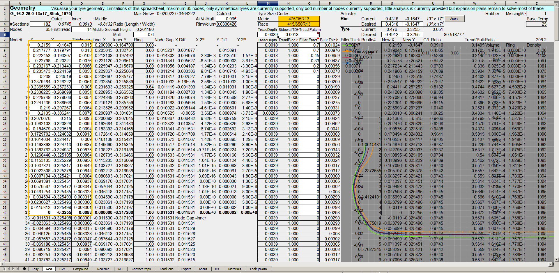
The Brabham’s rear tyres profile in the spreadsheet. On the right is the visual representation, the text beneath is of low importance and thus partially covered by the diagram.
Construction
The next part is the tyre construction itself. Broadly speaking, this covers the materials, angles, and thicknesses. This is certainly one of the most difficult areas, and will also be very difficult to access data regarding. If you happen to be doing bias-ply tyres, they’re simpler. Likewise, road tyres at least list some of the construction materials used on the sidewall. Certain design traits can also inferred from what it written on the sidewall. Let’s look at an example, “Sidewall: 1 Rayon, Tread: 1 Rayon, 2 Steel, 1 Nylon”. The “Tread” materials are those found in the middle of the tread or center of the tyre crown. “Sidewall” materials are those found half-way up the sidewall. Meaning that it won’t include chafer plies or turn-up plies (except in rare cases where the turn-up plies extend far). For the record, turn-up plies are simply the ends of the casing that wrap around the bead for added strength. We know that because there is only 1 “Rayon” layer, that particular tyre will have a 90 degree ply angle, because it is listed in both the sidewall and tread. A tyre also has to behave roughly symmetrically, with some slight exceptions. If there were 2 Rayon plies, they could be at non-90 degree angles, by opposing the angles they would counter act any thrust. Generally twin ply carcasses are placed at equal opposing angles. I have seen tyres with 3 plies in the sidewall, this is where things become more confusing. It’s possibly they need 3x 90 degree plies for stability. But it’s more probable that one is 90 degrees and the others are opposing. It’s also possible one is a chafer that reaches quite high into the sidewall. So, you may need to get more creative. In the spreadsheet, construction details are entered from cells Geo.C90 and onward. Nylon tyre cords (thread, strings, rope, or whatever you want to call them) are among the most common in racing tyres. They are commonly available in anything from about 0.4mm to 0.8mm diameter for tyre cords. That doesn’t mean they can’t be thicker, or thinner, though. I chose to go with 0.69mm diameter cords for now. Given they are bias-ply tyres, the construction has to be strong enough to resist the tyre folding in. The spacing values should be roughly 30-150% greater than the diameters of the fibers. In reality, this is necessary to prevent fatigue resulting from cords rubbing. Steel cords will normally have a greater spacing than fabric cords. In the case of nylon cords, typical spacing are around the 0.8-1.5mm range. The Brabham tyres were set to 1.05mm, giving a clearance between strands of 1.05-0.69=0.36mm.
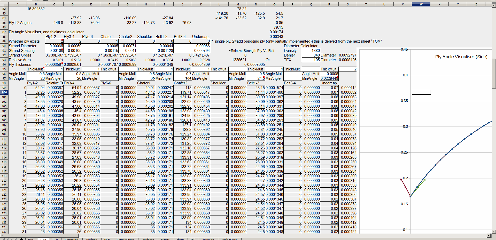
“TGM Gen V0.29” basic construction details.
Further construction details are edited on sheet “TGM”. This covers most of the important ply construction materials. It also allows you to specify the reign or span of plies. It also lists the test conditions that tTool uses when generating lookup tables. These are entered from C9 to C29. As the tyres are still an early in development, it’s not necessary to specify more than 2 gauge pressure values, 2 temperatures, and 2 rotation speeds. Flaws in the tyres are likely to show up without the need for more extensive and detailed tests, and this speeds up the process. In the future, when you are satisfied with the overall tyre characteristics, building a larger, more complete lookup table may bring about some small benefits. For this case, that will occur when the Brabham is close to final, probably next week. Construction materials are listed in TGM.C35+. It is difficult to explain what everything does, so be sure to read the comments provided in the spreadsheet. If you have done all these steps, you should be able to begin generating a basic .tgm file within tTool. However, this post is getting quite lengthy and I will elaborate further on the process next time around.
To repeat, be sure to read the cell comments throughout the spreadsheet, as *most* of them have somewhat detailed descriptions. However, if you feel the spreadsheet is lacking in that department, let us know by making your own comments below. It may make the difference for future versions. Likewise, agree, disagree, or just found something interesting about anything I said? Got some additional reading or suggested books for people learning? Feel free to post some comments!

