So far we covered the most basic import of rF1 style physics into rF2, followed by most of the HDV and TBC parameter updates / improvements. Now, it’s time to tackle the improved internal combustion engine model.
However, to start off this entry, a little something I forgot the last time around. In the HDV, under the 4 sections, from [FRONTLEFT]-[REARRIGHT]. We have another variable to add.
SpringAux=(0,0.0) // Auxillary spring (<allowNegativeSpringForce>,<helperSpringRate>).
                  // Allow the normal spring to produce negative forces (0 to disable),
                  // optional helper spring which is "always on".
Though, this most likely will not have any noticeable effect on the BT44. Springs would formerly go negative if you had enough rebound travel (stretching the spring), which usually isn’t particularly accurate as not many cars have clamped or welded springs. However, most modern cars already have some preload (the rebound stop), as such for those, this doesn’t have significant influence over vehicle dynamics. Furthermore, the damper tends to “stop” the wheel travel extending beyond this point anyway. So under most conditions, the effect will be very minor. Nonetheless, it has now been incorporated. The parameter also allows helper springs, as the 2nd parameter, but those are irrelevant to the BT44, so we’ll ignore them.
The Engine.ini
So on to the juicy topic, the engine file. How is the engine model different? In short:
- The new model allows throttle map adjustments. This can be achieved through 2 methods (or a combination), volumetric efficiency and fuel-air mixture manipulation (the latter is more directly related to diesel engines).
- Allows fuel mixture adjustments and this can lead to better fuel consumption controls. This requires the latest build (B1098).
- Engine braking maps also have greater control / freedom.
- Allows turbocharged engines.
- In theory has support for air pressure / density changes, although the latter has not been utilised. It does mean that we’re able to simulate ram air through a more accurate pressure increase, though.
We won’t need everything for the Brabham, but I’ll outline how it works. To start with, I’m going to copy the torque curves from the engine.ini and “import” them into my spreadsheet. I’m using the “rF2 Physics Calculator V0.22” (rF2PC) spreadsheet is available at the rFactor.net’s dev corner. V0.22 should be available shortly, and has been updated to fix a few minor bugs. LibreOffice Calc allows a basic text import, which will do nicely for us, allowing us to paste the data without having to type it manually or copy every single line. After opening the Cosworth_DFV_1975.ini, copying all lines that start with “RPMTorque”, they can be ‘special pasted’ into a blank LibreOffice sheet. Simply press CTRL+SHIFT+V (shift activates the special paste) to paste into LibreOffice. This will bring up a prompt called text import. Select “Separated by” and select “Other”, entering manually “(,)” as in this screenshot below:
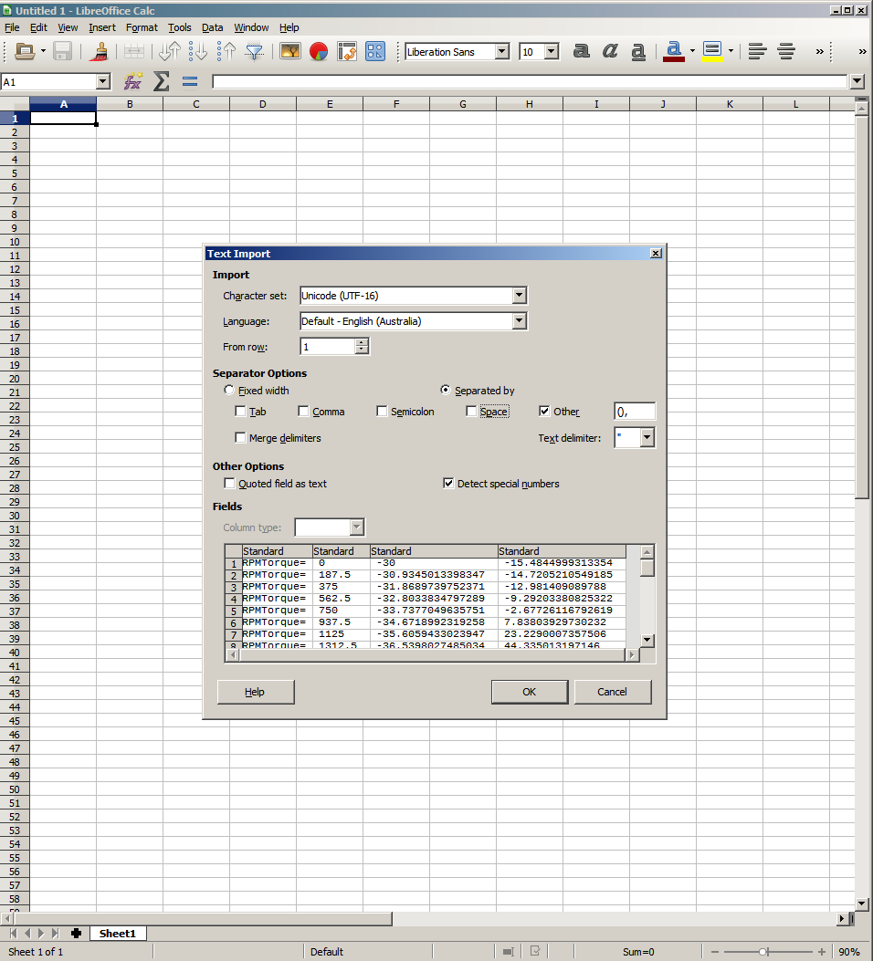
A special paste with “(,)” tells the software to treat these characters as separate tabs.
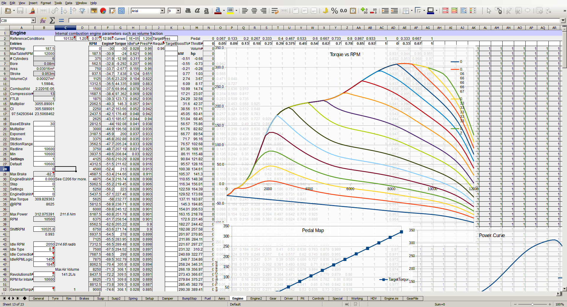
We just need to copy the last 2 columns of data and paste them into the ‘rF2PC’ spreadsheet. Simply go to the engine sheet, and paste into cell F4. This will replace some formula, but that’s OK in this case, where I believe the original engine braking torque values are at least somewhat accurate. Now we need to change the RPM step to match, “187.5”, the MaxTableRPM to “12000”. We also have to set the max RPM to 10600 (redline RPM) in order for the automatic calculations to work properly. Finally, we need to look at the idle values, which were formerly:
IdleRPMLogic=(1800,2200)
Clearly the intent was an idle of about 2,000RPM, which matches my knowledge of the Cosworth DFV. Though in-game testing shows the idle was 1966RPM. A quick search has revealed a great resource, and awesome read here. Which indicates an idle above 2,000RPM for the DFV.
Essentially, the purpose of all this is to replace the old values of:
RPMTorque=( 0 , -30 , -15.4844999313354 )
Which I will define here. RPMTorque1 defines the RPM. RPMTorque2, the braking torque (completely off the throttle). And RPMTorque3 is the torque at full throttle for this RPM. Values in-between RPM steps are smoothed by rF2 automatically.
The roughly equivalent replacement of which looks like (I will not be pasting the entire table here):
RPMBase=(0,-30,-30,0.0339,0.96)
VolumeFract=(0,1,1,1,1,1,1,1,1,1,1,1,1,1,1,1)
MixtureFract=(0,0,0,0)
Ideally, for the first point in the data, the ‘peak torque should match the ‘brake torque’. Which is why it’s slightly different. Defining RPMBase=(V,W,X,Y,Z), where V is the RPM, W is the maximum engine brake torque, X is the maximum torque, Y is the idle throttle application (minimum throttle applied) Z is ‘pressure power’. Pressure power represents the power change in the engine vs air pressure changes. It represents a mathematical power of the current air pressure over the reference conditions (see a couple paragraphs below).
VolumeFract, is the volumetric efficiency per throttle step, up to 16 entries. The first and last entry are always minimum and maximum throttle. So in this case, each value represents an increment in throttle of 1/15 or ~6.7%. Essentially, it’s the amount of torque you get, as a fraction of the RPM base 3rd and 2nd values. If VolumeFract is 0.5 and the brake torque is -30 while the positive/peak torque 100 at that RPM, you’d end up with about (-30*(1-0.5)+100*0.5), 35Nm, of positive torque. With a VolumeFract value of 0.8 you’d have (-30*(1-0.8)+100*0.8) 74Nm of positive torque.
MixtureFract operates much the same as VolumeFract, but it uses the engine mixture to achieve torque adjustments. I will elaborate on those a bit further in.
At the top of the file we must have:
ReferenceConditions=(101325,1.225,0.073) // pressure (pascals), density (kg/m^3),
                                         // fuel/air mass ratio, the presence of
                                         // this line activates the new engine model.
These reference conditions activate the new engine code in rF2. Pressure is the ambient pressure of the specified RPM base values that you’ve defined. The same goes for density, which is the air density, and the fuel/air mass ratio. Most power curves are generated in maximum power mode, which usually entails a somewhat rich mixture with an air-fuel ratio of about 12.5-13.5:1. Let’s say 13:1, we can reverse this to a fuel-air ratio to 1:13, or 0.077 in rF2’s measure. Methanol or other blends can alter this optimum significantly. The optimum for fuel efficiency could be around 1:15.0-15.5.
With this all said and done, my spreadsheet looks something like:
More stuff to add to the engine:
FuelDensity=0.74
FuelAirMixtureTable=(0.0, 0.091)
FuelAirMixtureEffects=(0.0, 0.0)
FuelAirMixtureEffects=(0.1, 0.11)
FuelAirMixtureEffects=(0.2, 0.22)
FuelAirMixtureEffects=(0.3, 0.33)
FuelAirMixtureEffects=(0.4, 0.44)
FuelAirMixtureEffects=(0.5, 0.55)
FuelAirMixtureEffects=(0.6, 0.66)
FuelAirMixtureEffects=(0.7, 0.77)
FuelAirMixtureEffects=(0.8, 0.88)
FuelAirMixtureEffects=(0.89, 0.99)
FuelAirMixtureEffects=(0.98, 1.0)
FuelAirMixtureEffects=(1.0, 0.97)
FuelAirMixtureEffects=(0.97, 0.9)
FuelAirMixtureEffects=(0.85, 0.8)
FuelAirMixtureEffects=(0.65, 0.6)
FuelAirMixtureEffects=(0.4, 0.4)
FuelAirMixtureEffects=(0.1, 0.1)
FuelAirMixtureEffects=(0.0, 0.0)
What does it do? Well fuel density is the mass of fuel, per liter. In this case, 1 liter of fuel weighs in at 0.74kg.
FuelAirMixtureTable=(<>,<>) Start, and step size of fuel/air ratio (normalized relative to reference mixture) for following table;
FuelAirMixtureEffects=(<torque multiplier>,<exhaust gas temperature multiplier>)
Basically, at each step, this defines a torque multiplier for the torque output by the engine, and also the exhaust temperature. From rF2’s perspective 2nd value is really only relevant to turbocharged engines.
A new parameter, related to the above:
EngineMixtureRange=(1.0, 0.1, 1) // Engine fuel-air mixture shift from baseline.
                                 // Affects fuel consumption and torque / power,
                                 // essentially a multiplier of current
                                 // "MixtureFract" tables.
EngineMixtureSetting=0
This shifts the entire MixtureFract table as defined previously in the engine.ini. It is adjustable on-the-fly (in-car). I will not be using it at this stage for the BT44 as I don’t believe the driver had any real control over what the engine was doing. It would have been risky. Lower values basically lean out the fuel mixture, and higher values make it richer. 1.0 is the default (0.073 in this case) fuel-air mixture, a value of 0.9 would give a fuel-air mix of 0.9*0.073=0.062 (15.22:1 AFR).
As the idle throttle is now adjusted per RPM step (through RPMBase4 values), the following line is obsolete:
IdleThrottle=0.4
The following values enable launch control:
LaunchEfficiency=1
LaunchVariables=1
Altered to:
LaunchEfficiency=0
LaunchVariables=0
Simply because this car does not, have a launch control system.
Another new line:
RevLimitHardTime=0.0
Sets a time threshold for the redline ignition cut.
The following:
OptimumOilTemp=110
Is replaced by:
OilTemps=(0.2,110)
The 2nd value is the same, it basically sets the thermostat temperature, when the engine oil heat exceeds 110-10=100°C, the thermostat will open to cool the engine block with water heat transfer through the radiator. The first value is new, however, and is a fraction between the current ambient temperature, and the optimum engine temperature. Many engines are used with block heaters to maintain a safer temperature before going out on track.
EngineEmission=(0.00, 0.0,-0.0)
EngineSound=( 0.00, 0.0,-0.0)
These values are not obsolete, but were never correctly configured. They represent the X,Y,Z location, relative to the rear axle centerline at the reference plane (remember ISI units are X=lateral, Y=vertical, Z=longitudinal).
EngineEmission=(0.0, 0.2,-0.4)
EngineSound=( 0.0, 0.2,-0.0)
The engine was missing a few lines, regarding ram air that were available in rF1. Thus, the following lines were not in the previous file, but I will illustrate them regardless:
RamCenter=(0.0, 0.9, -1.2) // location of ram air intake
RamDraftEffect=3.0 // multiplier for effect that draft has on ram air velocity
RamEffects=(2.0e-5,2.0e-5,2.0e-5,2.0e-5) // torque % increase per m/s,
                                         // power % increase per m/s and RPM,
                                         // fuel increase per m/s,
                                         // engine wear increase per m/s
The new values are:
RamCenter=(0.0, 0.9,-1.2)
RamDraftMult=5.6
RamPressure=(0,4.0e-6)
RamCenter, is the X,Y,Z location for ram air effects.
RamDraftMult, is the draft air speed multiplier. Utilization of this parameter exaggerates the drafts’ air speed (see my previous blog, radiator draft mult), thus decreasing overall engine power for the car behind. This is significantly above 1 because, A) air from the car ahead can be rather turbulent. B) it has been warmed by the car ahead (less dense), and C) it’s safe to assume that some of the oxygen has been spent by the car ahead for combustion.
RamPressure, now, instead of a direct influence on torque / power, ram air now builds up air pressure at the intake. It also, more accurately, allows this change to occur with the square of speed, as opposed to the old method which only allowed for a linear control with speed. RamPressure1 represents the linear pressure increase with the speed (in m/s). RamPressure2 represents the exponential increase with air speed or increase in intake pressure with speed squared m/s². So at 180km/h (50m/s) we have an increase in pressure of 4e-6*50^2. Approximately 1% increase in air pressure.
The Gearbox
What’s new? We have the ability to restrict gear ratios to specified gear indexes (such as 1st gear, or 2nd gear). But first, I believe the old ratios were not particularly accurate. Trawling the internet, the Brabham BT44B had a standard gearbox of the time, a Hewland FG400. I came across a nice resource:
Originally Posted by http://hewlandclassic.com/assets/manuals/fg_400.pdf
Crown Wheel & Pinion 7:31
Crown Wheel & Pinion 9:31
Crown Wheel & Pinion 8:31
Crown Wheel & Pinion 10:31
Whereas, the original values were:
[FINAL_DRIVE]
bevel=(20,32) // 1.6
ratio=(9,31) // 3.4444
ratio=(9,30) // 3.3333
ratio=(10,31) // 3.1
ratio=(10,30) // 3
Thus we’ll update them to:
[FINAL_DRIVE]
bevel=(1,1) // 1
ratio=(7,31) // 4.429
ratio=(8,31) // 3.875
ratio=(9,31) // 3.444
ratio=(10,31) // 3.1
As this car does not appear to have a separate bevel gear as such. The final drive gears are already beveled and thus account for the axis change of the torque vector (the engine spins around the roll axis, while the wheels spin around the pitch axis). I could have also used a special entry “FinalDriveSpecial” to define these ratios, but in this case there are no drawbacks to using the older “GearFile” method. Some cars have both bevel and final drive ratios adjustable, would very well benefit from using FinalDriveSpecial overrides, as it would allow you to create all the possible ratio permutations.
Another rather useful resource, particularly for Hewland gear ratios is available here. Digging through this site, the FG gearboxes evidently use the FT gear ratios. We can use that to fill in the data in the GearFile, and will also enable us to enact restrictions on gear ratios. On this site, “Std” gears can be used from 3rd ratio onwards. “2nd” can only be used for 2nd gear. And Integral “1st” can only be utilized as a first gear ratio. I will incorporate all of these into the GearFile, rather than as special overrides, simply because the new method would involve redundant entries.
In the HDV, under the [DRIVELINE] section what we end up with is:
Gear1Range=(0,0,6)
Gear1Special=(0,,,"13,46")
Gear1Special=(1,,,"12,38")
Gear1Special=(2,,,"12,35")
Gear1Special=(3,,,"13,35")
Gear1Special=(4,,,"14,34")
Gear1Special=(5,,,"14,33")
Gear1Setting=0
Gear2Range=(0,0,13)
Gear2Special=(0,,,"14,33")
Gear2Special=(1,,,"14,32")
Gear2Special=(2,,,"15,33")
Gear2Special=(3,,,"15,32")
Gear2Special=(4,,,"15,31")
Gear2Special=(5,,,"16,32")
Gear2Special=(6,,,"16,31")
Gear2Special=(7,,,"16,30")
Gear2Special=(8,,,"17,31")
Gear2Special=(9,,,"17,30")
Gear2Special=(10,,,"17,29")
Gear2Special=(11,,,"18,30")
Gear2Special=(12,,,"18,29")
Gear2Setting=5
Simply put, special instructions here allow us to allocate each gear. The ratios themselves must be in quotes. All special entries follow the format:
*Special=(<Index>,<non-translated value prefix>,<translated value postfix>,<instructions>)
Index is simply the entry you would like to replace the default values of. Essentially for non-translated value prefix, you can specify value of the display you’d like to show in the garage page, or leave it blank to use the defaults (recommended for gear ratios). Translated value postfix I would generally use the display unit. <Instructions> are special instructions to override the physical values. They can be unique for different sections of the HDV or engine files. For example, gear ratios need to take 2 entries, for example “17,29” which represent the teeth on the input, and output shafts respectively. The final drive ratio version takes 4 parameters, the first 2 being the bevel gears. If I were to add them for the BT44 the first entry would look something like FinalDriveSpecial=(0,,,”1,1,7,31″).
As always, the latest BT44B is already up on steam and likely already downloaded to your machine (if you’ve subscribed).

