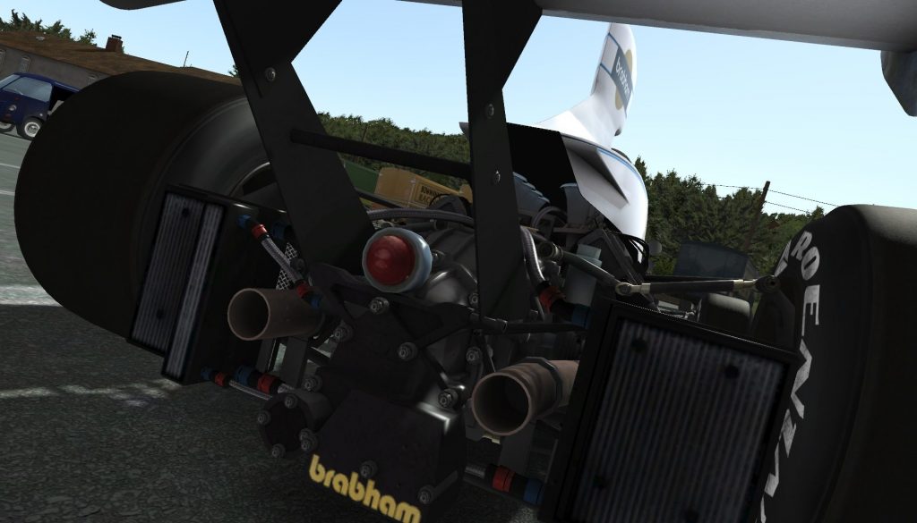
So last week, I covered the absolute (or near enough) minimum to get the physics to work in rF2, from an rF1 base mod. This week, continuing with the Brabham BT44B, we’re getting rid of a bunch of old lines, replacing some and adding a few newer ones. Some provide tiny corrections to calculations, or use more complex algorithms to solve problems more accurately. Others allow a bit more freedom. As good practice, it’s a good idea to clear out as much irrelevant or obsolete parameters as possible. Scrolling through the .HDV file, I will outline each parameter, that has been added, replaced, updated or defuncted. As I briefly touched on last time, our physics engineer, Terence, has worked very hard to ensure backwards compatibility. As such, these changes are optional, but can bring about certain benefits, the purpose of which I shall try to illustrate. We will proceed section by section.
[GENERAL]
The first line that can be replaced comes under the [GENERAL] section, and this is:
FuelTankPos=( 0 , 0.15 , -1 )
In this case, we have a newer version that is actually split into 2 parameters. FuelTankPosFull= & FuelTankPosEmpty=. If you hadn’t worked it out by their names, the fuels’ CG (centre of gravity) now migrates between a full and empty fuel tank. This represents a tiny influence on overall vehicle dynamics for a heavy GT car, but in a grand prix car (such as this), changes in fuel can be more influential. Let’s break down why, the car is 650kg, with a fuel tank size of 41 imp. Gallons, 186.4L. The specific weight of fuel is about 0.74kg/L, the fuel weighs in around 186.4*0.74=~138kg. As a portion of the vehicle mass, that’s 138/(650+138)=~0.175. This means, with a full tank, ~17.5% of the cars’ weight is fuel! As fuel is spent from the tank, the influence it has on the overall vehicle CG also reduces. By the time you get to an empty tank it has no influence on the CG at all. This means, using a weighted average, a properly configured version of FuelTankPos=, would have assumed an approximately 75% full fuel tank, or perhaps better yet, 75% of the typical starting fuel load (for certain series’ which don’t necessarily run full tanks). If we look at the first value of FuelTankMotion=(490.5,0.67), 490.5 N/m is the spring rate, per kg of fuel. 1kg of fuel weighs 9.81N, so just sitting there, the fuel has moved 9.81/490.5 = 0.02m downward due to gravity. Therefore the effective CG of the fuel is 0.13m above the reference plane, with the older variable. If we assume a 10mm clearance between the bottom of the chassis and the bottom of the fuel tank, an empty tank would give us a 0.13-0.01=0.12m change in height. A full tank will double that, (1/0.5)*0.12+0.01=0.25m. If I were to assume the calculation was done at 75%, (1/0.75)*0.12+0.01=0.17m. To correct for the movement we need to add that 2cm back to the vertical height of both variables, so what we end up with is:
FuelTankPosFull=(0, 0.19, -1)
FuelTankPosEmpty=(0, 0.03, -1)
These values are quite plausible, given the triangular shape of the fuel tanks. A triangle has its CG at 1/3 of its height (assuming the lower 2 co-ordinates share the same height). The BT44 essentially has 3 fuel tanks, 2 in the ‘sidepods’ and one behind the driver. Yes, the driver was effectively surrounded by fuel. Calculating a proper CG will be difficult, but it looks like we have a good base.
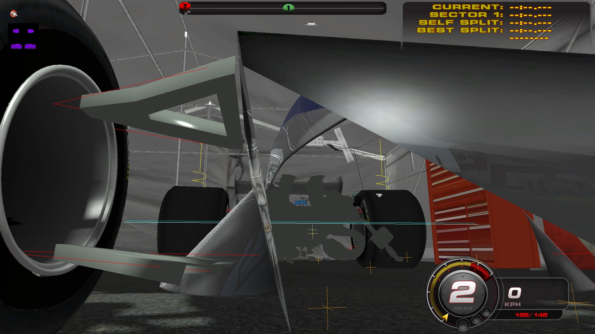
This screenshot shows how the fuel tank location looks in-game. To view this mode, press CTRL+U in developer mode. There are additional display options here, pressing CTRL+U again will disable vehicle body rendering, the last display will be an engine power / torque curve, which may also be of interest. The yellow cross-hair is the current fuel CG, while the gray cross-hair is the origin. The blue lines represent the center of gravity, both total and body only. While taking the screenshot, I noticed there was an orange cross-hair in limbo. These orange cross-hairs are undertray points which you can find a bit lower in the HDV file. The BT44 was only using 11 of the available 12 undertray points. Generally, more will give a better collision response with the ground, as the cars shape is better represented.
From:
Undertray10=( 0 , 0 , 0 )
To:
Undertray10=( 0.25, 0, 0)
Undertray11=(-0.25, 0, 0)
With any luck, this might allow the car to ‘catch’ more accurately on sharp terrain edges, like embankments, tall curbs or rough grass.
Next up, another supersession, quite optional again:
CGHeight=0.238
Replaced by:
CGHeightRange=(<base>,<stepsize>,<steps>)
This feature was required by our Go-Kart implementation in rF2. Those vehicles allow seat height adjustments and this is an important tuning option for them. Go-karts are very unique in that they have locked rear axle and limited adjustability. They don’t have a true suspension, and are extremely light too. For these reasons, they are unique in that they don’t always want the lowest possible center of gravity. Full-size racing cars by contrast, virtually always want the lowest possible CG, and thus this feature is probably irrelevant to anyone reading this (unless you happen to be working on your own karts). I will use the newer variable regardless, but it makes no difference in this case.
We end up with (the equivalent value of):
CGHeightRange=(0.238,0,1)
CGHeightSetting=0
Next we scroll down to:
AISlipReaction=(650,20)
This particular line is obsolete, and so can be safely removed.
Next up on our radar is:
AIAimSpeedsPerWP=(25,50,75,97,120,145,170,190)
You may choose to copy these values to your talent (.RCD) file. In all likelihood though, they can probably be improved and may not even work as well in rF2 as they did in rF1. If you do want to copy these, the best way is by starting in dev mode and loading a circuit with your vehicle. Once the track has loaded, go on track, Pressing CTRL+\ with bring up the AI editor and selecting the “Edit Driver Stats” option will bring up the relevant parameters. There you can ‘Create New Driver’, which will generate a new .RCD file (if one doesn’t already exist). Select the driver “default” and enter the previous values, as the speed step values. Note the first value is “StepDistance” and was hard-coded to 5 meters in rF1.
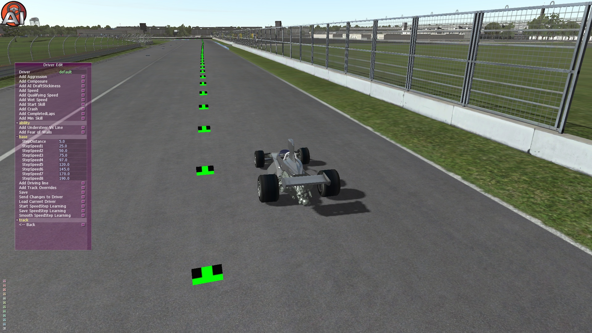
This is what the Brabham driver talent (.RCD) file, looks like now.
Completely obsolete:
AICornerReductionBase=180
We can safely eliminate this line from the .HDV file.
AIMinPassesPerTick=10
While this is not obsolete, I will briefly cover it. While higher is ‘better’ it does cost us some processing power. This is not recommended as it might take people with lower end systems over the edge of being able to run in real-time, and that’s really bad news. Generally, AI will already look fluid with values of 4, and in practice this works well with softly sprung vehicles. Really stiff cars or cars with a lot of aero that tend to run on bumpstops are sometimes in need of an increase here to cope. So in general, try to get away with the lowest value you can.
Anyway, it has now been changed to:
AIMinPassesPerTick=4
AIRotationThreshold=0.25
Defaults to 1.0 in rF2, it’s no longer really a necessary parameter, so I’m removing it from the BT44. This variable increases passes per tick by 1 when the AI exceed this yaw rate (rad/sec) intended to give the AI slightly higher fidelity physics in corners, basically. But if you have a AIMinPassesPerTick value of 4 or higher, then this is unnecessary.
AIEvenSuspension=0
Is completely obsolete, say hello to our old friend, the delete key. In short, it was formerly a hack for the AI that could be used to improve their stability. Use of this variable would increase the disparity between AI and player physics, hence we no longer offer the option to use it.
AISpringRate=0.9
Has been replaced by:
AICornerRates=(0.9,0.9,0.9,0.9)
Basically, does the same thing as the old parameter. More intelligently however, it allows us to manipulate the AI’s spring rate per corner of the vehicle. Because the AI run a simplified suspension, this should factor in the motion ratio squared from each wheel. The motion ratio is essentially the ratio of wheel displacement vs damper shaft displacement (assuming a coil-over). The ordering is <FrontLeft>,<FrontRight>,<RearLeft>,<RearRight>, and we’ll continue to use the old value of 0.9 everywhere, for now.
AIDamperSlow=0.8
AIDamperFast=0.8
Replaced by:
AIDamping=(1.0,1.0,1.0,1.0)
If you use the old variables, (which do still work), the AI will remain using a simplified damper. This improves their correlation by giving them more human-like dampers, we’re going to stick with 1.0 multipliers. Note that damping rates are already multiplied by “AICornerRates”, which means you can hopefully stick with 1.0 values for all cars.
AIDownforceZArm=0.0
AIDownforceBias=0.75
In theory, these haven’t changed, but hopefully with some subtle improvements in the AI’s physics we might be able to change AIDownforceBias=0.75 to 0, which gives us a better correlation with player physics. Basically, it’s a hack to move the AI’s aerodynamic downforce distribution. AIDownforceBias 1.0 tells the game to put the aero distribution at a fixed hard-coded location, based on the weight distribution, for which AIDownforceZArm acts as an offset to. While AIDownforceBias=0.0 gives us the most human like aerodynamics. If AIDownforceBias is 0, then it’s irrelevant what you do with AIDownforceZArm, it has no effect. It can sometimes be useful as a tuning agent when AI experience either high speed understeer, or oversteer. High-speed understeer can often be cured or improved by moving downforce bias forward. If AIDownforceBias is set to 1 and AIDownforceZArm set to 0, it will place the center of downforce at the vehicles’ center of gravity. Generally race cars are designed and setup with the downforce behind the center of gravity, in the realm of 2-15% behind (with larger disparities possible in very low downforce, or positive lift vehicles). The AI may not always react perfectly to that, though as their suspension, despite improvements, remains simplified to reduce CPU utilization.
Completely obsolete:
AITorqueStab=(1.0,1.0,1.0)
This was an old hack, no longer needed, it’s been hard-coded to 1.0. Delete.
Completely Obsolete:
FeelerFlags=0
FeelerOffset=(0,0,0.262636)
FeelersAtCGHeight=1
FeelerFrontLeft=( 0.7 , 0.22 , -2 )
FeelerFrontRight=( -0.7 , 0.22 , -2 )
FeelerRearLeft=( 0.45 , 0.77 , 2.1 )
FeelerRearRight=( -0.45 , 0.77 , 2.1 )
FeelerFront=( 0 , 0.22 , -2.1 )
FeelerRear=( 0 , 0.22 , 1.7 )
FeelerLeft=( 0.7 , 0.22 , 0 )
FeelerRight=( -0.7 , 0.22 , 0 )
FeelerTopFrontLeft=( 0.82 , 0.22 , -1.5 )
FeelerTopFrontRight=( -0.82 , 0.22 , -1.5 )
FeelerTopRearLeft=( 0.99 , 0.22 , 1.56 )
FeelerTopRearRight=( -0.99 , 0.22 , 1.56 )
FeelerBottom=( 0 , 0.27 , 0 )
As the collision feeler system was replaced by a generally better mesh based system. For rFactor 2, it’s recommended to remove these lines.
[FRONTWING]
FWLiftHeight=(0.5)
Replaced with:
FWLiftHeightPlus=(0.0,0.5,0.0)
The old value allowed only a linear variation in downforce with changes in front wing height (above the ground). The new version allows a Square root relation to ride height, in addition to squared relation. The value I used here is equivalent to the old value, but this allows a bit more power / freedom should we need to change it in the future. Aerodynamic data is hard to come by for older vehicles but we’ll have to investigate this in the future.
[BODYAERO]
There are few changes here. But the HDV was missing a couple rF1 entries,
DraftBalanceMult=1.0
BodyDraftLiftMult=1.0
We’ll add them now, in the event that we might need them in the future.
In addition, we now also have:
RadiatorDraftFract=1.5
A new feature for rFactor 2, allows draft to interfere with the engine cooling of any car that may follow. What this variable does is to multiply the difference in air-speed due to draft. Therefore, it will mostly affect the car behind. We choose values above 1.0, because we can assume that the air coming off the car retains some additional heat (race cars get hot). In addition, turbulent air flows usually reduce cooling efficiency some. In practice, a 50% exaggeration (1.5) seems to correlate well with most cars, it should probably always be above 1.0.
One section was previously commented out (disabled), and thus falls back to defaults. I speak of:
//BaseDropoff=0.18
//LeadingExponent=80.00
//FollowingExponent=1.75
//VehicleWidth=2.10
//SideEffect=1
//SideLeadingExponent=2.0
//SideFollowingExponent=3.5
Additionally, BaseDropoff= has been superseded by BaseDropoffLeadFollow=(<lead>,<follow>). The main reason for this addition is that open wheeler aerodynamics behave somewhat dissimilarly to closed wheel type race cars (particularly sedans / GT’s). The leading wake of open wheelers tends to be much weaker due to a lower frontal area. Additionally the frontal area is broken up and sporadic. A little research from our previous vehicles (namely the Dallara DW12 and FISI 2012) has shown that for an open-wheeler the leading value should be approximately half of the following value. The BaseDropoff= generally tended to be configured with a greater emphasis on accuracy of the trailing draft. Therefore I will use the following values for the BT44, for now:
BaseDropoffLeadFollow=(0.09,0.18)
For sedans or GT’s, you might want to keep the same or similar values for both the lead and follow component.
Going down the list, “//LeadingExponent=80.00” was set this way to prevent sudden snap oversteer when a car followed too closely in an open wheeler. The proper fix has been the improved parameter outlined above, and no longer do we need to exaggerate this value to prevent such issues. LeadingExponent=2.2 it is.
//FollowingExponent=1.75, the default is 2.0, and that’s what I’m going with for now.
VehicleWidth=, this variable, should be roughly the width of the car, maybe a little bit higher. The car’s track width at the rear is 1.5494m (61 inches, ref: statsf1.com). According to our trusted source of last week, the rear tyres are approximately, 476mm (ref: Avon). It’s always good practice to get at least 2 references to any claim, as errors do crop up. And no, that doesn’t simply mean going to 2 sites like Ultimatecarpage or Conceptcarz, as they both usually use the same source and are often a copy / paste of each other.
SideFollowingExponent is the only other variable I will alter, our default of 3.5 is probably inappropriate for most vehicles. I’m using about 20 for this car.
The section now looks like:
BaseDropoffLeadFollow=(0.09,0.18)
LeadingExponent=2.2
FollowingExponent=2.0
VehicleWidth=2.10
SideEffect=1.0
SideLeadingExponent=2.0
SideFollowingExponent=20.0
A visual representation of which, in-game looks something like:
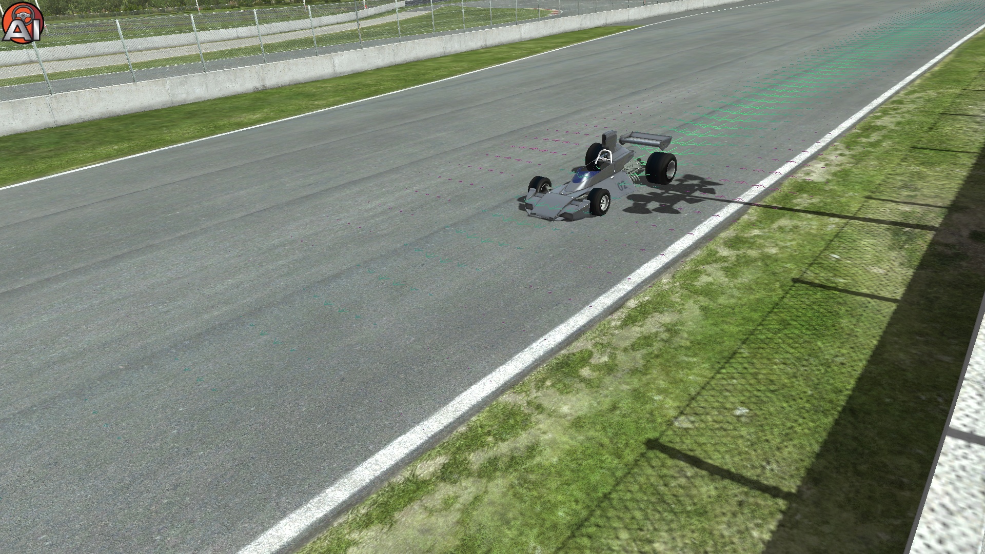
You can view how these parameters affect the draft while driving around in dev mode, by pressing CTRL+Z. The aqua arrows are ‘forward’ draft, reducing drag, while the purple arrows are areas where other vehicles will see an increase in effective air speed, and thus, drag.
[DIFFUSER]
DiffuserBase=(-0.5,-4,16)
DiffuserBasePlus=(-0.5,0,-4,16)
The new values are <Base (1st as before)>,<SquareRoot (New)>,<Linear (2nd)>,<Squared (3rd)>.
DiffuserFrontHeight=(1.5)
DiffuserFrontHeightPlus=(0,1.5,0,0.16)
New variables are with front ride height <SquareRoot (New)>,<Linear (Old)>,<Squared>,<Max Front Height>. Max front height acts like a cap, the rest are multiplied by the diffusers’ current front ride height. I’m using 0.16 as the max height used for the front diffuser height.
This:
DiffuserDraftLiftMult=1.4
Had a bug in rF1, whereby it wasn’t working properly. So in rF2, you may want to make sure it is configured properly, I’m setting it to 1.0 which basically maintains the effective air speed while in draft, for lift calculations. The old value would exaggerate the effective air speed due to draft, on the lift coefficient of the diffuser by 40%. Say we were headed at 100mph, and the car behind was going close enough that the effective air speed was 90mph, due to the effect of draft. Continuing on, that represents a change in air speed of 10mph, which would have been exaggerated as a 14mph draft on the lift coefficient. Every “*DraftLiftMult” parameter follows the same logic.
[SUSPENSION]
Out with the old:
CorrectedInnerSuspHeight=-1
And in with the new:
CorrectedInnerSuspHeightAll=(0.00655,0.00655,-0.0067,-0.0067)
This allows individual control over each wheel (FL,FR,RL,RR), rather than the old behavior. This also contains a fix for live axle inner heights. -1 is not particularly accurate because the inner suspension heights would get changed based on the ride height setting in garage, for default ride heights, it should make no difference with properly configured files. How should it be set? The correct usage is to subtract the suspension design ride height (ground clearance) from the static tire radius.
The example using the BT44 would be, taking a look at the 2nd “Pos” value of the relevant wheel, in the .pm file (or ultrachassis.ini):
// Front wheels
[BODY]
name=fl_wheel mass=(16) inertia=(0.5419344,0.32774128,0.32774128)
pos=(0.7112,0.188,-1.456436) ori=(0.0,0.0,0.0)
Looking in the .TBC, for the front tyre the relevant values are:
Radius=0.254
SpringBase=20000
SpringkPa=1150
In the HDV, the default front ride height is:
RideHeightRange=( 0.045 , 0.001 , 11 )
RideHeightSetting=7
Giving us 0.045+0.001*7=0.052m
Using the same technique, the default pressures are 127 kPa.
The deflection or static tyre radius could be calculate from the weight acting on the tyre divided by the tyres’ spring rate. The vehicle is 650kg with 50% weight on the left side and 38.8% on the front axle, these can be multiplied with the acceleration due to gravity constant 9.80665. 650*0.5*0.388*9.80665 giving a result of ~1237N vertical load on the front tyre. The spring rate is 20000+1150*127=166050. The deflection of the tyre is therefore, 1237/166050=~0.00745
So, TyreRadius-TyreDeflection-WheelHeight(.pm file)-RideHeight
0.254-0.00745-0.188-0.052=0.00655
This is close enough to 0, that I will assume for the time being, that the car is simply running a lower ride height than it’s design parameters.
The same math yields a result of -0.0067 for the rear.
Following on:
FrontWheelTrack=0
RearWheelTrack=0
According to a few sources on the internet, the front track width is 56″ and the rear is 61″. So we can replace the above values with:
FrontWheelTrackRange=(1.4224,0,1)
FrontWheelTrackSetting=0
RearWheelTrackRange=(1.5494,0,1)
RearWheelTrackSetting=0
The change of track widths to a range allows wheel track adjustments, as possible in some cars via wheel spacers. This was added particularly for the go-kart, but has its uses with some other vehicles, too.
A more important one here:
SpringBasedAntiSway=1
AllowNoAntiSway=0
These have been replaced with:
FrontAntiSwayParams=(1, 0, 0)
And a separate one for the rear (RearAntiSwayParams). The values follow <SpringBasedAntiSway>,<AllowNoAntiSway>,<AllowOnbo ardAdjustments>. This allows different behavior for the front and rear anti-roll bars, which was not possible in rF1. The activation of the new 3rd parameter activates onboard / in-car adjustments to anti-roll bars. I do not believe they had in-car adjustable anti-roll bars in F1 in 1975, so I will set this to false unless I find anything that tells me otherwise.
Continuing on:
FrontAntiswayRange=( 20000 , 5000 , 9 )
FrontAntiswaySetting=2
RearAntiswayRange=( 0 , 5000 , 13 )
RearAntiswaySetting=4
This is not obsolete, nor have the variable names changed. However, the rates need to be divided in half. Why? rFactor 2 has changed from a stiffness at ground approach to more of a component stiffness or “AntiSymmetric Model”. This is all just a really complicated way of saying that you need 5,000N of force, on each side to change the wheel displacement of a 5000N/m anti-roll bar, by 1 meter between the left and right wheels, as each side now receives the full force. Each side requires 5,000N, one upward, the other downward, totaling 10,000N.
It would have looked like:
FrontAntiswayRange=(10000, 2500, 9)
FrontAntiswaySetting=2
RearAntiswayRange=(0, 2500, 13)
RearAntiswaySetting=4
However, after testing, I realized from a driving perspective that I preferred a stiffer ARB setup, while this is largely driver preference an anti-roll bar as firm on the rear as the front generally makes little sense. So I decided to allow a larger maximum front stiffness and set up the front accordingly. The rear is slightly softer than v0.11 overall, but still firmer than the original base.
The final values are:
FrontAntiswayRange=(10000, 2500, 13)
FrontAntiswaySetting=8
RearAntiswayRange=(0, 2500, 13)
RearAntiswaySetting=6
[CONTROLS]
A new addition to rF2:
SeatRangeLongitudinal=(-0.4,0.16) // Eyepoint camera longitudinal adjustment range
SeatRangeVertical=(-0.07,0.04) // Eyepoint camera vertical adjustment range
Allow you to change the adjustment range of the seat position. Defaults are -0.1, 0.1 for both variables.
TractionControlGrip=(1,0.15)
TractionControlLevel=(0.6,0.95)
ABS4Wheel=0
ABSGrip=(1.0,0.2)
ABSLevel=(0.4, 0.95)
Although functionally equivalent, we’ll replace it with:
TCRange=(0,0,1)
TCSpecial=(0,,"Aid (Weight Penalty)","TC=(1.0,0.15,0.6,0.775,0.95)")
ABSRange=(0,0,1)
ABSSpecial=(0,,"Aid (Weight Penalty)","ABS=(0,1.0,0.2,0.4,0.95)")
The *Special= overrides are not something I have covered yet. They allow special instructions and garage display overrides. Different parameters allow different special instruction. In this case, “TC=(1.0,0.15,0.6,0.775,0.95)” is formatted in relation to the old parameters as, TC=(<TractionControlGrip1>,<TractionControlGrip2>, <TractionControlLevel1(Low)>,<TractionControlLevelMedium(New)>,<TractionControlLevel2(High)>). Traction control grip variables basically define the slip at which TC begins to engage. A better name might be ‘predicted slip curve slope’ or something like this, with the first value essentially being the slope gradient multiplier, while <TractionControlGrip2> is basically an offset, and positive values assume the tyres always have some grip. Increasing either ‘grip’ variables allows TC to engage later allowing more slip in the car. While the traction control levels basically adjust how much torque to cut when the tyre is slipping. It’s basically the maximum torque reduction that TC will allow. <TractionControlLevelMedium> is a new entry that allows you to override the TC level with “Medium” aid setting. 1 is for “Low” traction control and 2 is for “High” traction control. The only actual new functionality is that A) unlike before, you can change the medium TC level’s aggressiveness and B) you can now have garage adjustments to change these values. Because this car never had traction control in real life, I won’t be allowing any addition garage adjustments to be possible on the traction control (or ABS, as below).
ABS= follows a similar convention ABS=(<ABS4Wheel>,<ABSGrip1>,<ABSGrip2>,<ABSLevel1> ,<ABSLevel2>). “ABS4Wheel” is whether we use 4 separate channels for the ABS system or 1 channel. All cars that don’t have a real ABS system should have “ABS4Wheel” disabled, as it would basically allow vectoring different wheels based on individual grip levels. That could basically be considered a cheat as humans only have 1 brake pedal to play with.
Finally, we can also add this:
PitcrewPushForce=750
MarshalPushForce=750
The former tells the pit-crew how much force they can use to push the car, when it’s out of fuel in pitlane for example. The latter is how much force track marshal’s are able to use if you get stuck somewhere. 750N is about what we’d expect for a couple of average people.
[ENGINE]
This is following line is completely obsolete:
RestrictorPlate=Cosworth_DFV_1975.ini
Anything that you could have done here, can be done (better) through the upgrades.ini. You still need “Normal=Cosworth_DFV_1975.ini” to point to the right file, of course. At this stage, it’s looking likely that the next blog will cover the engine file in-depth, so stay tuned!
[FRONTLEFT]-[REARRIGHT]
I will cover these sections as a whole, because they duplicate parameters. In other words, every parameter under [FRONTLEFT] can be duplicated under [REARRIGHT] or any of the other 2 wheel sections. This means a single explanation can be applied to all 4 sections.
First up:
BumpTravel=0
ReboundTravel=-0.11
With:
BumpStopTravels=(0,-0.11)
A small improvement to the calculation of motion ratios has been done, making the bump-stop positioning more accurate. The bumpstop heights assume a ride height of 0. So the wheel can move up to -0.11m (negative being a downward direction) from the current 0 ride height before hitting the rebound stop, because the default ride height is 0.052m, the rear rebound travel is 0.058m from the static height.
SpinInertia=0.5419344
SpinInertiaAI=0.55
SpinInertia is obsolete, as part of the new “ModelWheelsinIncludeTireMass=1” variable (covered last week). SpinInertiaAI is still available, but we recommend to delete both. The default is to use the same as the player gets, meaning a closer correlation. Previously in rF1, the default behavior was to double the SpinInertia of the player vehicle when running AI physics (for stability reasons). Running AIMinPassesPerTick above 3 or 4 usually alleviates the need for this in all but the most extreme vehicles. However, before deleting it, one thing to check first is whether it matches with the first “Inertia” value in the .pm (or ultrachassis.ini file) for that particular wheel.
In this case that section looks like (with the relevant parameter in bold):
// Front wheels
[BODY]
name=fl_wheel mass=(16) inertia=(0.5419344,0.32774128,0.32774128)
pos=(0.7112,0.188,-1.456436) ori=(0.0,0.0,0.0)
People had a tendency to set SpinInertia correctly, but not its equivalent form in the .pm file, which was neglected because it was previously overridden by SpinInertia. If it didn’t match, I would have changed it (the bolded text) to match whatever value the SpinInertia had. In the end, SpinInertia was, 0.5419344 which is a match that defined in the .pm file. It’s important to check the remaining 3 corners as well. It is especially important to make sure the inertia’s of the wheels are set appropriately as this can lead to stability issues in rF2.
The rears are:
SpinInertia=1.439222928
SpinInertiaAI=1.44
Which also matches the .pm file. Therefore, there’s no need to change anything on that front.
TBC
Before I end this weeks’ session, let’s open up the TBC (AI tyre model and reference) and update that as well.
Firstly, we need to consider the effect that real-road rubber has on grip. Grip now increases with the road surface rubber. As cars generally used to be configured as having optimal track grip levels, we’ll need to reduce the base grip coefficients under, DryLatLong. To do so, we’ll need to open the TGM files, and look for the line GrooveEffects=(0.1,0.1,0.083,0.057). We need to find a sort of average that will work for the TBC, the 3rd value is usually close to that average, because of the way track surfaces are designed. So we’ll use 0.083 and we’ll assume the mod was designed for a 90% saturated track in mind, but we’ll also assume another 1% loss (which will come from GrooveSqrdEffects= line, not currently in the .TGM). In the end we’ll need to divide the current grip coefficients (DryLatLong), by (0.083-0.01)*0.9+1=1.0657.
Secondly, we’re missing the WetLatLong=(<Lateral>,<Longitudinal>), variable. It is now only used for some seldom used aids, like braking help, but it is still be wise to include this. What to set it to? Well, it would be quite complicated to match perfectly, because the TGM variable depends on many things, fortunately, this isn’t terrible accurate and for slicks a value of about 0.7x the dry value works quite well. The front tyre looks like:
DryLatLong=(1.72887,1.67634)
WetLatLong=(1.2102,1.1734)
RoadGripEffects=(0.083,-0.1,-0.16,-0.36)
RoadSqrdGripEffects=-0.01
RoadModifierMults=(0.5,0.8,0.8,0.5)
I’m using for the first value RoadGripEffects, I’m using the 3rd entrant of GrooveEffects=, from the .TGM value.
For the 2nd value, “MarbleEffectOnEffectiveLoad=-0.1” from the .TGM.
For the 3rd value, the 3rd value from “DampnessEffects” in the .TGM file.
Finally, for the 4th value, “TemporaryGripLossForWetness=0.36”. The RoadModifierMults, are multipliers for the real-road rate, say, if you have a rubber that particularly marbles up, or whatnot. Eventually, I will go through aspects of the .TGM file and explain the rationale behind some of these .TBC multipliers, too.
These are out:
AIPeakSlip=0.09
AITireModel=1.0
AITireModel is now hard-coded to be 1.0, as the tyres are exclusively for the AI, and also it more closely resembles a typical tyre slip curve. A value of 1.0 there, also nullified AIPeakSlip.
Finally, in their place we can add:
AIHeatRate=7.5e-6
AIPitThreshold=0.85
These were technically around in rF1 as well, AIHeatRate is how quickly the AI tyres get up to temperature (with the default being 6.6e-6). AIPitThreshold=0.85 is how much grip left, due to wear before the AI finally gives up on their tyres.
This is not a comprehensive guide, and this could be seen as complimentary information to the comments provided in the SkipBarber.hdv, which is included with the developer SDK (if you’ve migrated to Steam, it’s included, with the default path of C:\Program Files (x86)\Steam\steamapps\common\rFactor 2\ModDev\Vehicles\SkipBarber). Or you can download the SDK from the rFactor 2 website. On the same website you can also check out “rF2 Physics Calculator 0.21 ODS | Information – Feb 15, 2016” which has a complete parameter listing, although slightly out of date (missing AIDamping= only, I believe). I will try and update that one as soon as possible. All feedback is welcome and I hope you enjoyed this record breakingly detailed changelog! If you haven’t yet, be sure to subscribe to the Brabham BT44B V0.17 on Steam. Don’t understand something? Don’t be shy, you can seek clarification in the comments section.

